Lab 4: Sum > Parts (Pupper Assembly)
Goal: Build a full Pupper robot! Lab 4 Document
Step 1. Prepare the bottom PCB
Note: You can skip this step if you completed your bottom PCB in lab 1
Remove the yellow cable (normally closed switch) from the power switch.
Solder the power switch cables into the bottom PCB. The two blue wires must be soldered into “Switch”, the red into “LED+”, and the black wire into “LED-”. Note: Make sure the wire ends are not electrically connected to each other.
Trim excess cable.
Attach 3D-printed protectors to electrically conductive areas on the bottom PCB.
Congrats! You finished the first step.
Step 2. Configure IDs and Calibrate the Motor Controllers
Assuming you constructed/calibrated two right legs and assigned them both IDs 1-3 in previous labs, complete the following for left legs.
For each left motor/motor controller pair:
Connect a motor to a motor controller, and the motor controller to the bottom PCB.
Ensure that the PCB is plugged into a power outlet, and turn the PCB on. If everything is properly connected, you should hear the motor controller beep.
Initiate calibration by holding the button on the motor controller until the motor begins to move (very slowly). Note: it is easier to tell that the motor is moving if you watch the white square on the bottom of the motor.
After calibration, reset the motor ID by pressing once on the button. After pressing down once, wait a bit and then press the button the nummber of times you want to set the new ID too (for example, if you want the new motor ID to be 6, press 6 times after the initial reset press).
Mark the ID number on your controller. DONT FORGET.
**NOTE: Correctly matching motor IDs and labelling is EXTREMELY IMPORTANT. If you do this incorrectly, you will later have to rebuild the robot.
Repeat these steps for all motors. Use this diagram to ensure you have the correct IDs set on your motor controllers. For each bulkhead you should have:
Right left/right motion hip motor: 1
Right forward/back motion hip motor: 2
Right knee motor: 3
Left left/right motion hip motor: 4
Left forward/back motion hip motor: 5
Left knee motor: 6
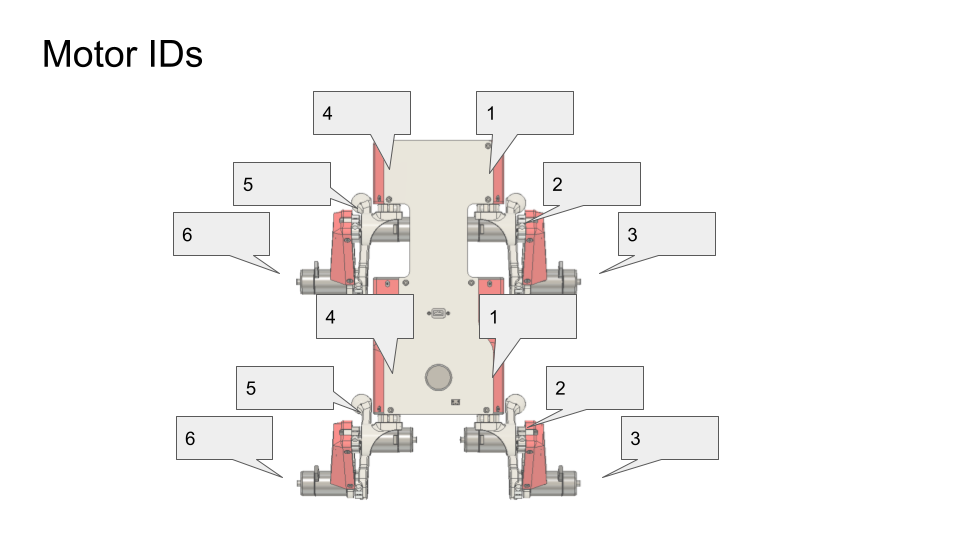
Motor ID diagram
**DELIVERABLE: Calibrating before constructing the motors is essential. Take a video of all 12 motors flashing green correctly and submit with the lab report. Why is it important to calibrate the motors before inserting them into the leg? **
Step 3. Assemble the legs
IMPORTANT: Calibrate your motors BEFORE attaching to legs. Please redo this step if legs were improperly constructed in Lab 2.
After completing calibration, it’s time to get started on the legs themselves! Insert a dowel pin into an upper leg. It should not protrude more than 0.5cm from the leg. Note: You can try pushing the dowel against the table to insert it, or using adjustable pliers.
Fit a square nut into the upper leg. You may have to push it in with a screwdriver. Ensure that the square nut alignment is correct by pushing a screwdriver through the shoulder screw hole into the square nut. There may be some loose filament in the way.
Install a motor into the upper leg using M3 flat head screws. IMPORTANT! The motor must have ID 3 if you’re working with the right knee, and 6 if you’re working with the left. Please refer to the above Motor ID diagram for more info. Make sure to orient the cables in the direction the arrow is pointing.
Attach the motor controller and fit it into the leg. Note: You will have to bundle the cables to squeeze it into the controller compartment. Secure loose wires with a long cable sleeve, and ziptie it on the end that goes into the controller compartment. Note: The ziptie is also pushed into the controller compartment before closing it.
Insert a square nut into the lower leg and ensure it is properly aligned. MANY STUDENTS FORGET THIS STEP.
Attach the lower leg to the upper leg. The hole on the lower leg should be aligned with the keyed part (flat part) of the motor shaft. TIP: Before screwing it in, ensure this alignment correct by pushing a screwdriver through the hole first.
Secure the lower leg to the upper leg with a 16mm shoulder screw. Note: Push the shoulder screw in as deep as possible before beginning to screw. If the shoulder screw is not flush with the side of the leg, the hole is not properly aligned and must be realigned. If the shoulder screw is flush with the side of the leg, great job!
Slide the long cable sleeve over the motor controller cable and secure one side with zip ties.
Encase the upper leg with the thigh section by pushing in the insert.
Fasten a motor to the hip bracket using M3 screws. IMPORTANT! The hip bracket you are using MUST MATCH the directionality of the leg. (Left leg with left hip, right leg with right hip). Also, the motor you are attaching is motor 5 if you’re working with the left leg, and motor 2 if you’re working with the right. Use the arrow to determine the appropriate orientation of the cabling. Insert the short cabling sleeve, and secure on one side with zipties.
11. Insert the short cable sleeving over the motor cable. Secure one side with zip ties. 2. Insert a square nut into the hip braket and make sure it is properly aligned with the shoulder screw hole using the screwdriver. 13. Secure the hip bracket to the upper leg. The flat part of the motor shaft should once again be aligned with the hole on the upper leg. Double check the hip side matches the lower leg side (R with R, L with L).
Repeat the above steps until you have 4 completed legs (2 left, 2 right).
**DELIVERABLE: Submit a photo of all 4 completed legs. **
Step 4. Attach the legs to the body
Apply the soldering tool to heat the M3 insert onto the motor bulkhead. Push inwards until it is flush with the surface.
Place 4 dowel pins into the corresponding holes on the motor bulkhead. Ensure the pins do not extend beyond 0.5cm from the surface.
Secure the motor bulkhead, ensuring that the arrow is directed towards the motor cable.
Insert the hip bracket onto the motor, ensuring that the flat surface on the motor shaft is facing outward. Utilize a screwdriver to align the hole on the motor shaft. Fasten the components together using the shoulder screw.
Fasten the cable to the motor bulkhead using zip ties, following the cable arrangement demonstrated in the video. This will prevent the cable from experiencing strain while the robot is moving.
Step 5. Attach legs to PCB
Secure the leg to the bottom PCB using an M3 button head screw.
Connect the power and signal cables of the motor controller to the PCB board. Make sure you have properly assigned the correct motor controller (As detailed in step 2).
Insert the motor controller into the motor bulkhead’s fin. Use zip ties to secure any remaining cables.
Repeat the process for the remaining motor controllers and organize the cables accordingly.
Activate the power to verify the ID settings are correct. All lights should exhibit a green blinking pattern.
Step 6. Attach electronics bulkhead to PCB
Screw RPi into electronics bulkhead with M2.5x5 socket head screws such that the Pi is oriented like in the video.
Connect USB C extension cable to Rpi
Connect RPi to power by using 2-pin cable. Connect one end into 5V, GND pins near the Teensy and other side into RPi. Quadruple-check that the 5V and GND pins are going the right places. See diagram.
Connect RPi to Teensy using USB A to USB micro cable
Connect RC receiver to RPi with usb extension cable.
Place front motor bulkhead
Connect motor controller power cables (yellow XT30) and CAN connectors (small white JST GH) to bottom PCB
Place back motor bulkhead and connect cables
Flip robot and fasten bulkheads to bottom PCB with 4x M3x6 button head screws
Tighten these screws well and/or add loctite
Step 7. Attach top PCB
Insert the XT60 female side (conductor is a circular slot) of XT60 splitter cable into 3D printed power hub.
Insert JST-XH extender balance cable into 3D printed power hub.
Attach the 3D printed power hub to the top PCB with 2 M3x6 button head screws.
Take the large nut off the power switch and then mount the power switch to the top PCB panel. Then secure the switch by threading on the nut from the bottom of the top panel.
Screw the USB-C connector to the top PCB with 2 M3x6 button head screws
Connect other female XT60 into the bottom PCB
Step 8. Bind RC receiver
Get a FRSKY USB receiver and a BetaFPV Transmitter
While holding the button on the USB receiver down, insert it into your computer. It should show a flashing red light.
Then turn on the transmitter: Press and hold the power button for about 5 seconds until twice vibration. The LED will be green first. Wiggle the left stick until the LED turns blue. Then the LiteRadio is powered on.
Press the BIND button from the back of the transmitter. The transmitter will enter the binding mode and last about 10 seconds, indicated by blue and red LED flash alternately.
Once bound, the receiver should then show a solid (not blinking) green color.
Unplug and re-plug the receiver into your computer and restart the transmitter. Then go to https://gamepad-tester.com/ in CHROME (no other browsers will work) to test that the receiver is receiving messages from the transmitter.
Refer to the transmitter manual for more info if needed https://support.betafpv.com/hc/en-us/articles/900003583046-Manual-for-LiteRadio-2.
Refer to the receiver manual for more info if needed https://www.frsky-rc.com/wp-content/uploads/Downloads/Manual/XSR-SIM/XSR-SIM-%20manual.pdf
Step 9. Finish hardware assembly
Put velcro or dual-lock onto the bottom PCB where it says “battery”. For now we’ll use the power supply to run the robot so you don’t have to install the actual battery.
Attach the top PCB panel with M3x6 button head screws.
Check again with instructors.
Marvel at your work!
Step 10. Flash code onto the Teensy
Go to https://github.com/Nate711/DJIPupperTests/blob/master/README.md for instructions on how to download and set up the Teensy firmware
Use VSCode PlatformIO to open the DJIPupperTests folder as a project and then upload the code to the Teensy. (Same thing as in labs 1-4).
Step 11. Flash software image onto Raspberry Pi
Download our image
Install Balena etcher
Flash the image onto the micro SD card using Balena etcher.
Insert the micro sd card into the Pi’s micro sd card slot (on bottom side of board)
Step 12. Enable the heuristic controller
Connect the robot to your computer via the top USB-C port on the robot.
SSH into the robot with
ssh pi@raspberrypi.local. The password israspberry. Ask for help if this doesn’t work.Run
sudo systemctl enable --now robotto turn on the heuristic controller.Run
sudo systemctl status robotto check that the service is running ok (should be green).Reboot with
sudo reboot 0
Step 12.5. Get Stanford Wifi access
Once ssh’d into the robot, run
ifconfigand record thewlan0MAC address. This is the MAC address for the WIFI chip. It should be a series of hex characters like f0:2f:4b:07:ee:ea.Go to iprequest.stanford.edu on your computer, and make a new registration for the Pi. Select other device -> other wired. Enter the Wireless MAC address you got in step 1.
Restart the Pi and SSH back in
Run
sudo raspi-config, go to System options -> Wireless LAN.Enter
Stanfordas the network name and leave password emptyYou might have to restart the Pi a few times, and use
raspi-configto set the desired network a few times for it to work.To test if the Pi now has internet access, run
ping www.google.com. It should say you’re getting bytes back from Google.If it doesn’t work, wait 20 minutes, restart the Pi, and try again!
Make sure you change the password after connecting to Wifi or it will get hacked. We highly recommend physically labeling the robot with the new password.
Step 13. Take your robot on a walk
Unplug the Pi from USB C.
Place your robot on a flat, level surface. Position the legs as shown in the picture below.
Power on the robot by hooking up the power supply to the bottom PCB (like you’ve done in labs).
Connect the Pi with USB C to your computer.
Wait for the robot to complete the calibration sequence. During the calibration sequence, the hips should turn inwards until they hit the stops, then back down. Then the thigh pieces should rotate upward until they hit their stops and then back down.
Flip all switches on the back RC transmitter down so they’re away from you.
Turn on the RC transmitter by pressing the middle power button and moving the left joystick up and down until the light turns blue.
Wait ~30s for the RPi to boot (the green light should stop blinking).
Flip the lower left switch on the controller up to enable the robot. It’ll move!
Flip the lower right switch on the controller up to start the robot trotting.
Enjoy your hard work and play with Pupper!
The top right switch flips between trotting and walking.
Left/right on the left joystick controls turning.
Up/down on the right joystick controls forward/back.
Left/right on the right joystick controls strafing left/right.
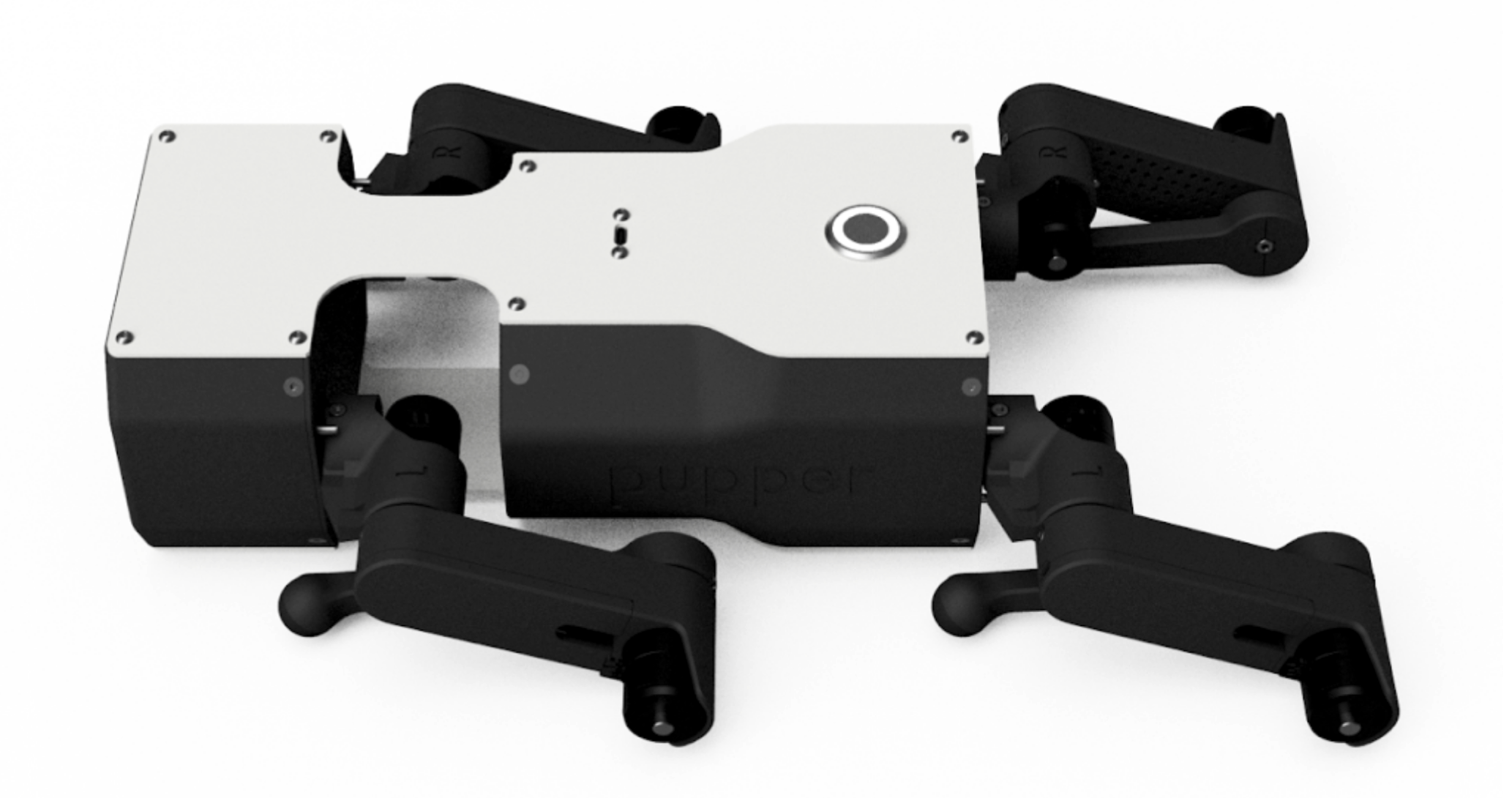
Startup position.
**DELIVERABLE: Take a video of Pupper walking around! **
<iframe src=”https://docs.google.com/presentation/d/e/2PACX-1vSOdXk8Tz55ZzrXGzIeHZUEigYQPUS2bPOIQPeFiRIXSRrVX7hqwXnC1yJnaZoH-uvJZ0OnK4JAW14o/embed?start=false&loop=false&delayms=60000” frameborder=”0” width=”600” height=”400” allowfullscreen=”true” mozallowfullscreen=”true” webkitallowfullscreen=”true”></iframe>